
What is a Three-Way Ball Valve? L-Port vs T-Port
Ultramax Systems on 16th Oct 2026
Short answer: A three-way ball valve has three ports and a ball drilled with an L-shaped or T-shaped bore, so turning the handle switches, splits or combines flow between the ports. It matters because the bore shape decides which ports can connect and whether the valve can shut off at all.
Why it matters
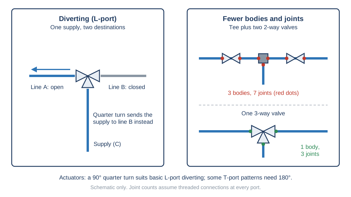
A three-way valve can do the work of several two-way valves. It can send one supply to either of two lines, switch between two supplies, or let you bypass a piece of equipment. One three-way valve can also replace a tee and two two-way valves, which cuts the number of joints and leak points (Collier 2026). The catch is that L-port and T-port valves behave very differently. Fitting the wrong one can leave a line open that you thought was closed. Leaks matter in compressed air, as shown in How much do Compressed Air Leaks cost?
How it works: L-port and T-port
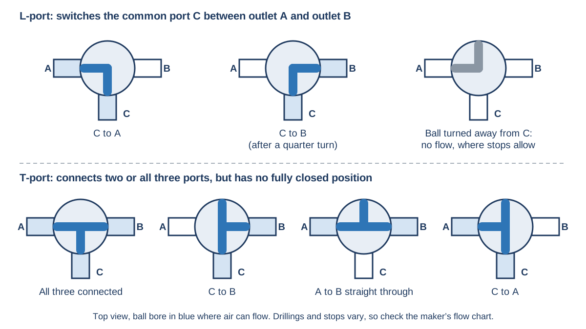
Each valve has a common port, often marked C, and two other ports. The ball turns inside the body, and its bore shape sets the flow path. An L-port ball connects the common port to one other port at a time. A quarter turn swaps it from one outlet to the other, so it suits diverting duty. It cannot blend two inlets into one outlet (Collier 2026). Turned away from the common port, an L-port ball can also stop flow, if the handle stops allow that position.
A T-port ball has a straight-through bore with a branch. Depending on its position, it can connect the common port to either side, join the two side ports straight through, or connect all three at once. That makes it suit mixing and bypass duty. However, T-port valves cannot shut off flow completely (Dixon Valve and Coupling Company 2025). Not every T-port opens the same combination of ports, so always check the maker's flow chart for the exact drilling and stops.
Typical types and applications
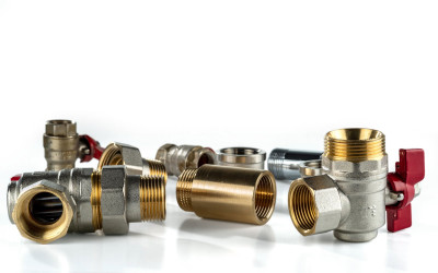
Manual three-way valves use a lever or tee handle. Ultramax stocks brass three-way ball valves in L-port and T-port versions, including side-entry patterns. Typical compressed air uses include switching a supply between two machines, changing over between two filters or dryers, and selecting between a main supply and a standby compressor.
Automated valves add a pneumatic or electric actuator. Actuated three-way ball valves come with double-acting or spring-return pneumatic actuators, or electric on-off actuators. Most actuators are sized for a 90° quarter turn, which covers basic L-port diverting or two-position T-port switching. Some T-port patterns, such as straight-through or all ports open, need 180° of travel instead. Specifying the wrong travel is a common and costly mistake (Collier 2026). Actuator mounting flanges and drive dimensions are commonly made to ISO 5211, the international standard for part-turn actuator attachments (ISO 5211:2026).
Australian practice: isolation
A three-way valve is a switching valve, not automatically an isolation point. Before maintenance, the plant code says isolation points should use devices that lock out the energy source, and that stored pneumatic pressure may need separate release (Safe Work Australia 2024). Because a T-port cannot close all ports, it should not be relied on to isolate a line. Use a lockable two-way isolation valve upstream, vent the line and confirm zero pressure before work starts.
Common mistakes and what to check
Confirm which port is the common port before fitting, and pipe the valve to match the flow plan. Check the handle or actuator stops against the positions you need. Check that the pressure rating suits the line, and note any seat sealing direction on the data sheet. Mount the valve so liquid or dirt does not settle in an unused leg. Finally, mark the handle positions clearly, so operators can see where the air is going.
Related terms
- Hard and soft seats: how the seat material affects shut-off. See What are Hard Seat and Soft Seat Valves?
- Mine valve: a heavy-duty two-way ball valve for mining air and water lines. See What is a Mine Valve?
- Refrigerated and desiccant dryers: where changeover and bypass valves often sit. See Refrigerated vs desiccant dryers.
References
- Collier, Vinnie. 2026. "Actuated 3-Way Ball Valve Selection: L-Port vs. T-Port for Diverting, Mixing, and Bypass Service." Assured Automation, 10 July 2026. Accessed 16 October 2026. https://blog.assuredautomation.com/actuated-3-way-ball-valve-selection-l-port-vs-t-port/.
- Dixon Valve and Coupling Company. 2025. "Understanding 3-Way Ball Valves." 11 June 2025. Accessed 16 October 2026. https://blog.dixonvalve.com/understanding-3-way-ball-valves.
- ISO (International Organization for Standardization). 2026. ISO 5211:2026 Industrial Valves: Part-Turn Actuator Attachments. Listing accessed via Austrian Standards, 16 October 2026. https://www.austrian-standards.at/en/shop/iso-5211-2026-2026-02-12~p4747726.
- Safe Work Australia. 2024. Model Code of Practice: Managing the Risks of Plant in the Workplace. Hosted by WorkSafe Tasmania. https://www.worksafe.tas.gov.au/__data/assets/pdf_file/0010/806734/model-Code-of-Practice-Managing-the-risks-of-plant-in-the-workplace.PDF.
This article is general information only. Check manufacturer documentation, applicable Australian Standards and your state or territory WHS regulator's guidance for your installation.