
How to size an Air Compressor for your Application
Ultramax Systems on 16th Oct 2026
Short answer: To size an air compressor, add up the free air each tool and process uses, scale it by how often each one runs, then add allowances for leaks and planned growth. Set the pressure from your most demanding user plus the pressure lost in filters, dryers and pipework. Finally, check the machine's rating for your site conditions and choose fixed speed or variable speed to suit your demand profile.
What you will achieve
By the end of this guide you will have a demand figure in litres per second of free air and a target discharge pressure to take to your supplier. Getting these right matters, because compressed air systems can use up to 30% of a site's electricity, and avoiding oversizing is key to getting the most from a high-efficiency replacement unit (Australian Government n.d.). An undersized machine brings the opposite problem: low pressure at the tools and a compressor that runs flat out.
Safety note
Measuring and installing a system involves pressure equipment. An air receiver may need design and item registration under the WHS Regulations, depending on its hazard level under AS 4343 (Safe Work Australia 2015). In Western Australia, pressure vessels at hazard level A, B or C under AS 4343 require registration, with some exclusions such as serially produced vessels (WorkSafe WA 2022). Leave pipework and electrical work to licensed, competent people.
What you need
- A list of every air tool, machine and process, with the maker's air consumption at working pressure.
- For an existing system, run hours and loaded hours from the compressor controller, or logged flow data.
- The minimum pressure each user needs at its inlet.
- Planned changes, and the hottest conditions in your plant room.
Step-by-step: sizing an air compressor
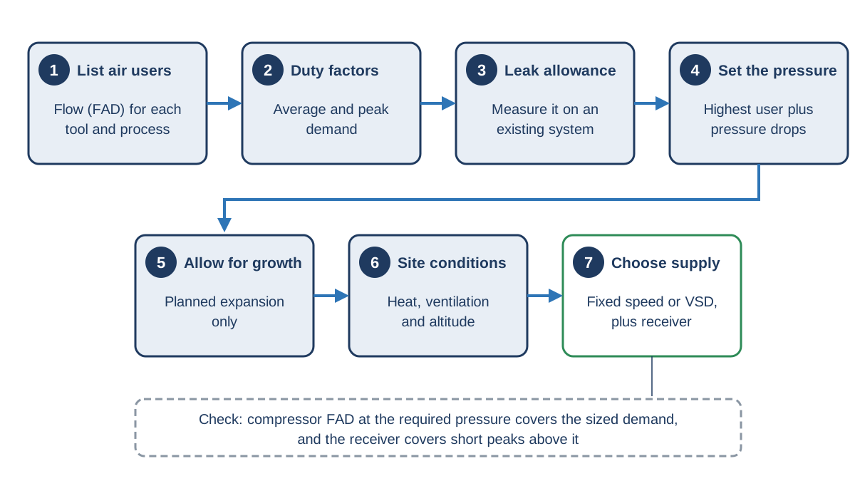
1. List your air users and their consumption
Start with every consumer: hand tools, machines, blow-off points and process uses. Atlas Copco (n.d.-a) recommends listing each one with its air consumption and expected utilisation, using standard values only where specific data is missing. Record consumption as free air delivery (FAD), the basis compressor makers use for their ratings.
2. Apply duty and diversity factors
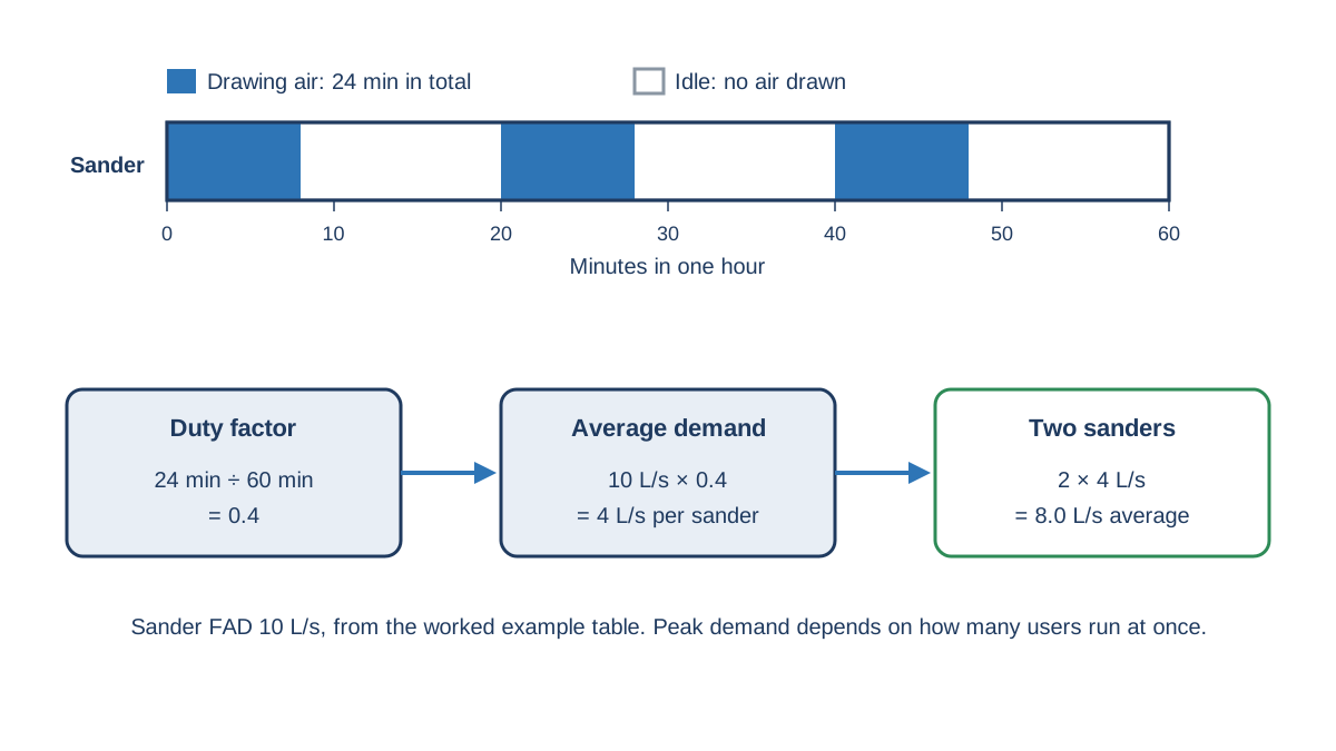
Few tools run continuously. A duty factor (or utilisation factor) is the share of time a tool draws air, so a sander used for 24 minutes in each hour has a duty factor of 0.4. Multiply each user's consumption by its duty factor to get average demand, then estimate how many users run at once to find the peak. Treat large users that run for several minutes at a time, such as grinders and blasting machines, as steady loads (Atlas Copco n.d.-a).
On an existing site, measure instead of guessing. Average flow can be estimated as the compressor's rated flow multiplied by its loaded duty cycle, timed with a stopwatch over several cycles (NSW Office of Environment and Heritage 2017). A week of data logged with flow meters gives a far better picture (Atlas Copco n.d.-a).
3. Add a leak allowance
Leaks run whenever the system is pressurised. Leakage of 20 to 30% of output is common in industrial plants (Compressed Air Challenge n.d.), and the NSW Office of Environment and Heritage (2017) puts typical losses at 25 to 45%. A new, well-built system justifies a smaller allowance. On an existing system, fix leaks before sizing a replacement, or you will buy a bigger compressor just to feed them. See How much do Compressed Air Leaks cost? for the numbers.
4. Set the pressure, including pressure drop
Pressure comes from your most demanding user, not the average one. Atlas Copco (n.d.-b) builds the minimum working pressure from the highest inlet pressure any user needs plus the losses on the way, then adds a margin for the control band. Typical drops are 20 to 50 kPa (0.2 to 0.5 bar) for refrigerant dryers, 30 to 70 kPa (0.3 to 0.7 bar) for desiccant dryers and 10 to 30 kPa (0.1 to 0.3 bar) for standard filters (Atlas Copco n.d.-b). As a check, the NSW Office of Environment and Heritage (2017) suggests the difference between the compressor outlet and the critical point of use should be no more than 10%.
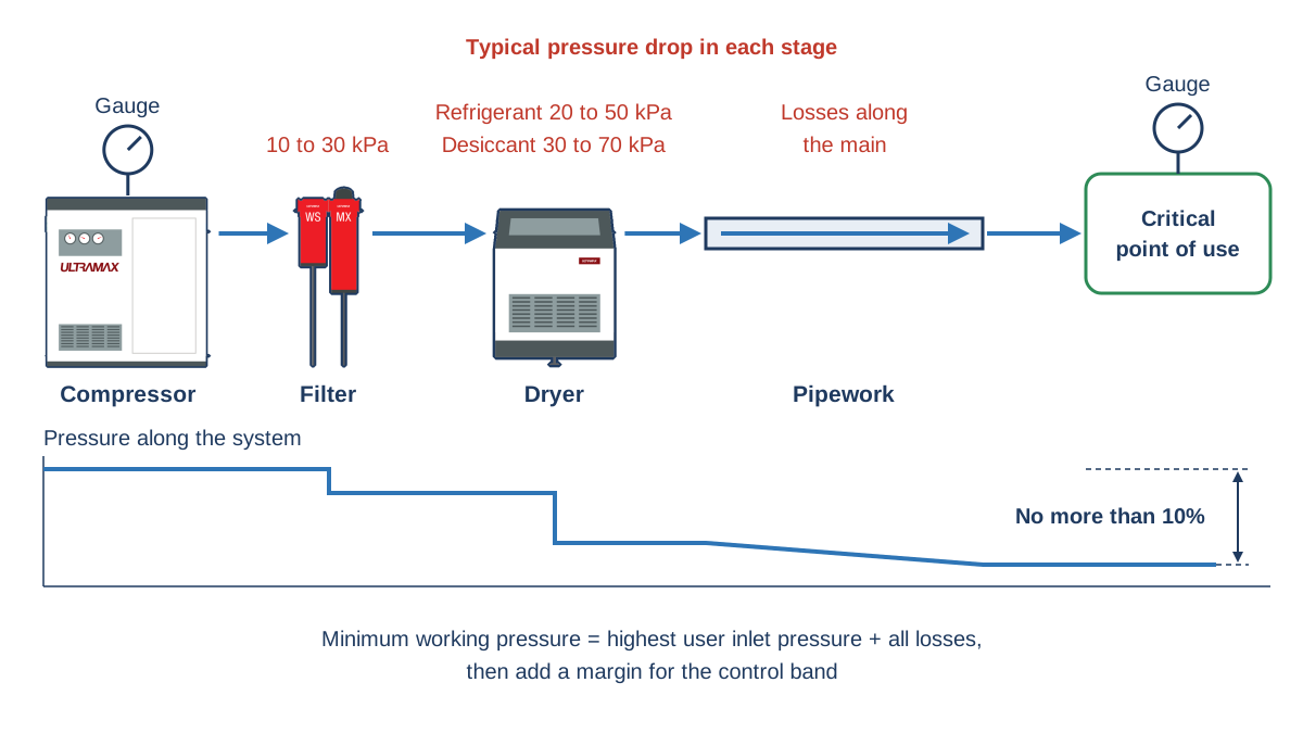
At 700 kPa (7 bar), a 15 kPa (0.15 bar) reduction in average pressure saves about 1% of loaded power (NSW Office of Environment and Heritage 2017). Pressure gauges at the compressor and the far end of the main show where the drop occurs.
5. Allow for growth
Size the supply for current conditions with an appropriate margin for expansion built into the installation (Atlas Copco n.d.-a). Base the margin on known plans, such as a new production line, not a blanket safety factor. A large margin pushes a single machine into inefficient part-load running for years. Where growth is uncertain, plan space and pipework for a second compressor instead.
6. Consider site conditions: heat and altitude
Australian plant rooms get hot. Most compressors are rated for a maximum ambient temperature of 40 °C, and almost all variable speed drives are built for the same limit, although some makers offer high-ambient packages for 50 °C or 55 °C (Sullair 2020). Above its rating, a machine may shut down on high temperature. Check the rating against the hottest conditions inside your plant room, and duct hot exhaust air away so it does not recirculate to the intake.
Altitude matters less at most Australian sites, but thinner air means each tool consumes more free air. Van Ormer and van Ormer (2022) recommend allowing for altitude in system design and confirming correction factors with the manufacturer.
7. Choose fixed speed or VSD, and size the receiver
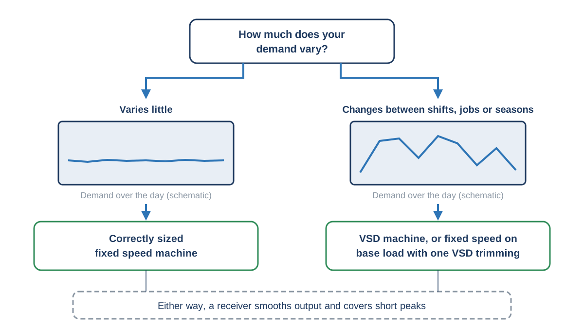
Your demand profile decides the compressor type. Where demand varies little, a correctly sized fixed speed machine may be more efficient and costs less to buy. Where demand changes between shifts, jobs or seasons, Atlas Copco (2022) favours a variable speed drive (VSD) machine, or fixed speed units on base load with one VSD unit trimming. A receiver smooths output and covers short peaks (Australian Government n.d.). See Air Receiver Sizing: Formula and Worked Example and Screw vs piston compressor for the next decisions.
Worked example: a small Perth workshop
The figures below are illustrative. Use your makers' data.
| Air user | Qty | FAD each (L/s) | Duty factor | Average (L/s) |
|---|---|---|---|---|
| Impact wrench (1/2 in) | 2 | 8 | 0.25 | 4.0 |
| Dual-action sander | 2 | 10 | 0.40 | 8.0 |
| Spray gun | 1 | 6 | 0.50 | 3.0 |
| Blow gun | 4 | 4 | 0.10 | 1.6 |
| Tyre inflator | 1 | 3 | 0.10 | 0.3 |
| Packaging machine | 1 | 4 | 1.00 | 4.0 |
| Total | 65 connected | 20.9 |
Assumptions: a new system, 10% leak allowance, 25% planned growth and tools needing 630 kPa (6.3 bar).
- Average tool demand: 20.9 L/s.
- Plus 10% leaks: 20.9 × 1.10 = 23.0 L/s.
- Plus 25% growth: 23.0 × 1.25 ≈ 28.7 L/s (about 1.7 m³/min).
- Pressure: 630 kPa + 20 kPa filter + 30 kPa refrigerated dryer + 20 kPa pipework = 700 kPa (7.0 bar) minimum. The 70 kPa (0.7 bar) of losses is 10%, at the NSW guideline limit.
- Add a 50 kPa (0.5 bar) control band: the compressor should deliver at least 28.7 L/s FAD at 750 kPa (7.5 bar).
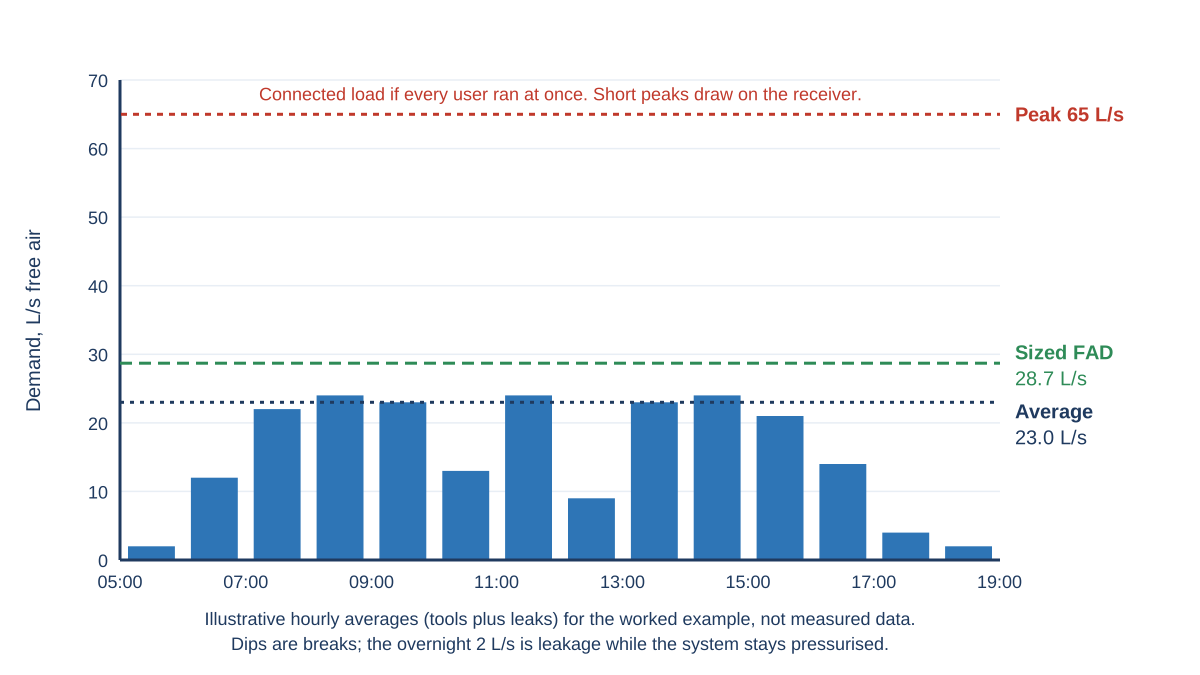
The 65 L/s connected load only occurs if every user runs at once, which is unlikely and brief, so the receiver covers those peaks. The profile also dips at breaks and overnight, which makes this workshop a candidate for a VSD machine.
Checks and common mistakes
The most common mistake is adding up nameplate consumption with no duty factors, which can produce a machine several times too large. Others include sizing around leaks, raising pressure to mask a pipework restriction and ignoring plant room temperature. Your compressed air dryer and filters must also suit the full compressor output at your hottest inlet temperature. After installation, compare loaded hours with your estimate.
When to call a specialist
Bring in a compressed air auditor for multi-compressor sites, large process loads, breathing air or any system where an outage stops production. A logged audit analyses peak and average flow to determine actual needs, as the Compressed Air Challenge (n.d.) recommends.
Frequently asked questions
Should I buy a bigger compressor just in case?
Not without a reason. An oversized fixed speed machine spends much of its time unloaded, wasting energy. Size for known demand plus planned growth.
Do I need a VSD compressor?
A VSD suits demand that varies widely through the day or week. If your profile is flat and close to the machine's capacity, a fixed speed unit may be the better fit (Atlas Copco 2022).
Related reading
- What is Free Air Delivery (FAD)?
- How much do Compressed Air Leaks cost?
- Screw vs Piston Compressor: Which suits your Workshop?
- Air Receiver Sizing: Formula and Worked Example
References
- Atlas Copco. n.d.-a. "Calculating and Measuring the Air Requirement." Compressed Air Wiki. Accessed 15 October 2026. https://www.atlascopco.com/en-lt/compressors/wiki/compressed-air-articles/calculating-and-measuring-air-requirement.
- Atlas Copco. n.d.-b. "Calculating the Working Pressure." Compressed Air Wiki. Accessed 15 October 2026. https://www.atlascopco.com/en-uk/compressors/wiki/compressed-air-articles/calculating-working-pressure.
- Atlas Copco. 2022. "When to Use a VSD Compressor." Atlas Copco USA blog, 20 July 2022. Accessed 15 October 2026. https://www.atlascopco.com/en-us/compressors/air-compressor-blog/when-to-use-a-vsd-compressor.
- Australian Government. n.d. "Compressed Air." energy.gov.au. Accessed 15 October 2026. https://www.energy.gov.au/business/equipment-guides/compressed-air.
- Compressed Air Challenge. n.d. Best Practices for Compressed Air Systems: Introduction. https://www.compressedairchallenge.org/data/sites/1/media/library/best_practices/Introduction.pdf.
- NSW Office of Environment and Heritage. 2017. Low Capital Cost, Simple Solutions to Improve the Efficiency of Your Compressed Air System. OEH2017/0257. Hosted by Energy NSW. https://www.energy.nsw.gov.au/sites/default/files/2022-08/2017_NSW_CompressedAirGuidepdf.pdf.
- Safe Work Australia. 2015. Compressed Air and Air Receiver Information Sheet. https://www.safeworkaustralia.gov.au/system/files/documents/1703/compressed-air-information-sheet.pdf.
- Sullair. 2020. "What's Possible When Operating Rotary Screw Air Compressors in Hot Ambient Conditions?" Compressed Air Best Practices, 30 April 2020. Accessed 15 October 2026. https://www.airbestpractices.com/technology/air-compressors/whats-possible-when-operating-rotary-screw-air-compressors-hot-ambient-c.
- Van Ormer, Hank, and Don van Ormer. 2022. "The Impact of Altitude on Air Compressor and Tool Sizing." Compressed Air Best Practices, 29 April 2022. Accessed 15 October 2026. https://www.airbestpractices.com/technology/air-compressors/the-impact-of-altitude-on-air-compressor-and-tool-sizing.
- WorkSafe WA. 2022. "What Kinds of Plant Require Registration." Last updated 30 March 2022. Accessed 15 October 2026. https://www.worksafe.wa.gov.au/what-kinds-plant-require-registration.
This article is general information only. Check manufacturer documentation and applicable Australian Standards for your installation.